
Distributed Synchronized Monitoring for System Disturbance Analysis in 500/220 kV Networks
Synaptec DES creates a distributed layer of synchronized current and voltage measurements for spatiotemporal analysis across geographically separated power-system nodes. It helps engineers reconstruct the sequence of a disturbance on one common time base and correlate the results with existing SCADA/EMS, PMU/WAMS, protection, remedial-action, and disturbance-recording systems.
Objective and practical result
When a system disturbance occurs, changes in network parameters must be compared at several remote locations. Engineering analysis must establish where the earliest change was recorded, how current, voltage, active and reactive power, frequency, and phase relationships then changed, and in what sequence adjacent nodes and automation responded.
DES does not automatically declare a root cause. It provides a synchronized measurement set that supports an engineering-confirmed sequence:
- pre-disturbance operating state;
- first registered change;
- propagation through the network;
- response of adjacent nodes, protection, and remedial-action schemes;
- post-disturbance operating state.
Basic measurement channel
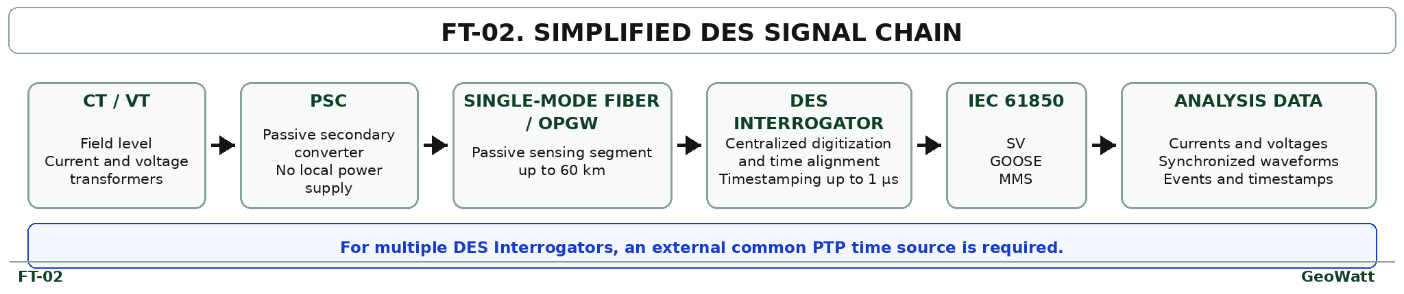
The measurement chain is: CT/VT → Passive Secondary Converter (PSC) → single-mode optical fiber or OPGW → DES Interrogator → synchronized digital measurements.
The remote PSC is passive. It requires neither local power nor active electronics at the monitored asset. Signal digitization, timestamping, and preparation for data transmission are centralized in the DES Interrogator.
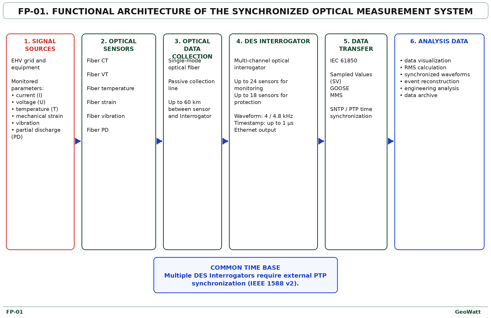
Synaptec DES functional architecture
Depending on the application, the platform can receive current, voltage, temperature, mechanical strain, vibration, and partial-discharge signals. For system-disturbance analysis in 500/220 kV networks, the primary data set comprises synchronized currents and voltages, waveforms, frequency, phase relationships, and diagnostic harmonic content.
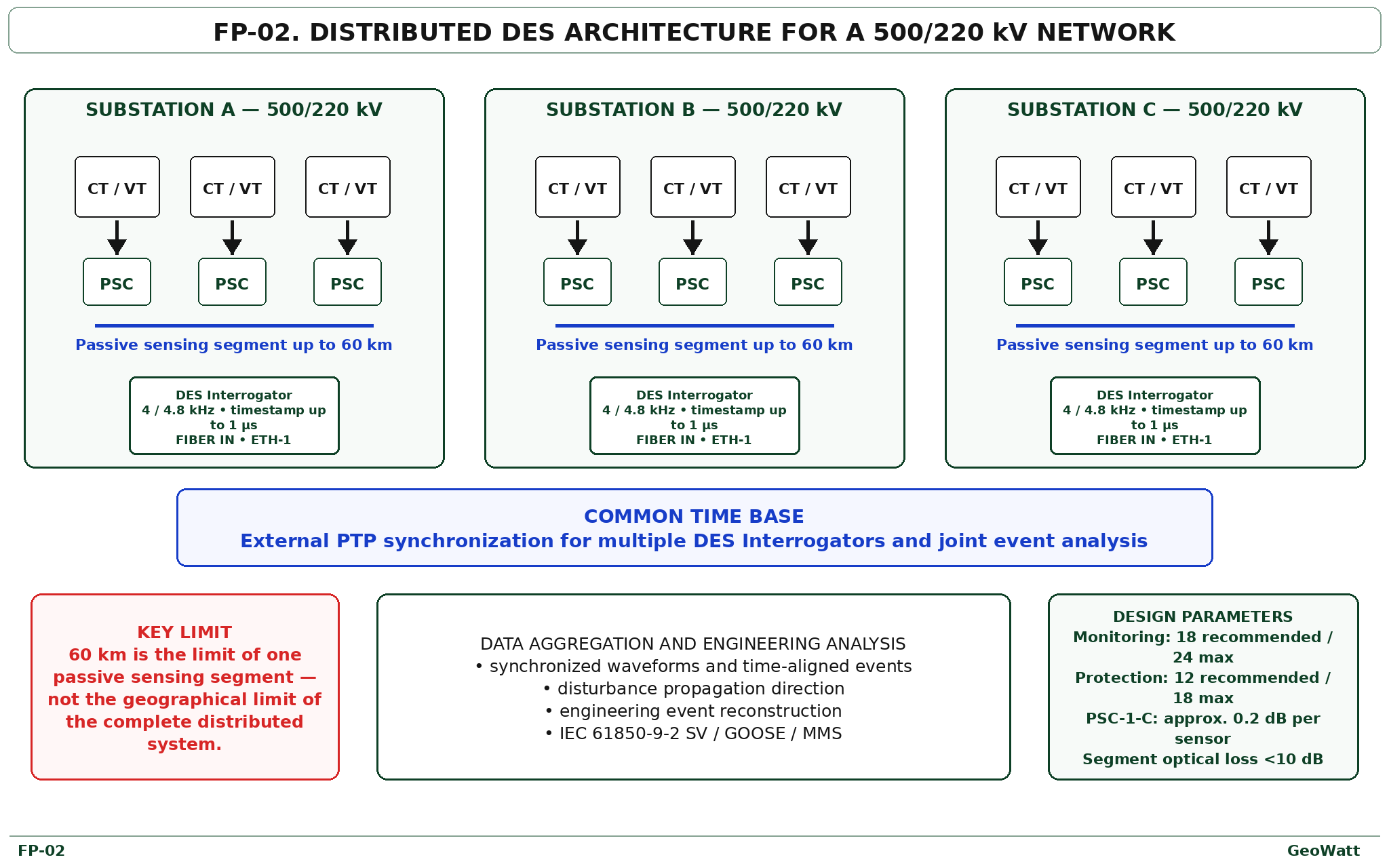
Distributed architecture for a 500/220 kV network
Each selected substation has its own passive measurement segment and DES Interrogator. Multiple geographically separated Interrogators share an external time reference, such as PTP, so all records can be analysed on one common time base.
The 60 km limit applies to one passive sensing segment—not to the complete distributed system. Wider geographical coverage is achieved with multiple segments and DES Interrogators.
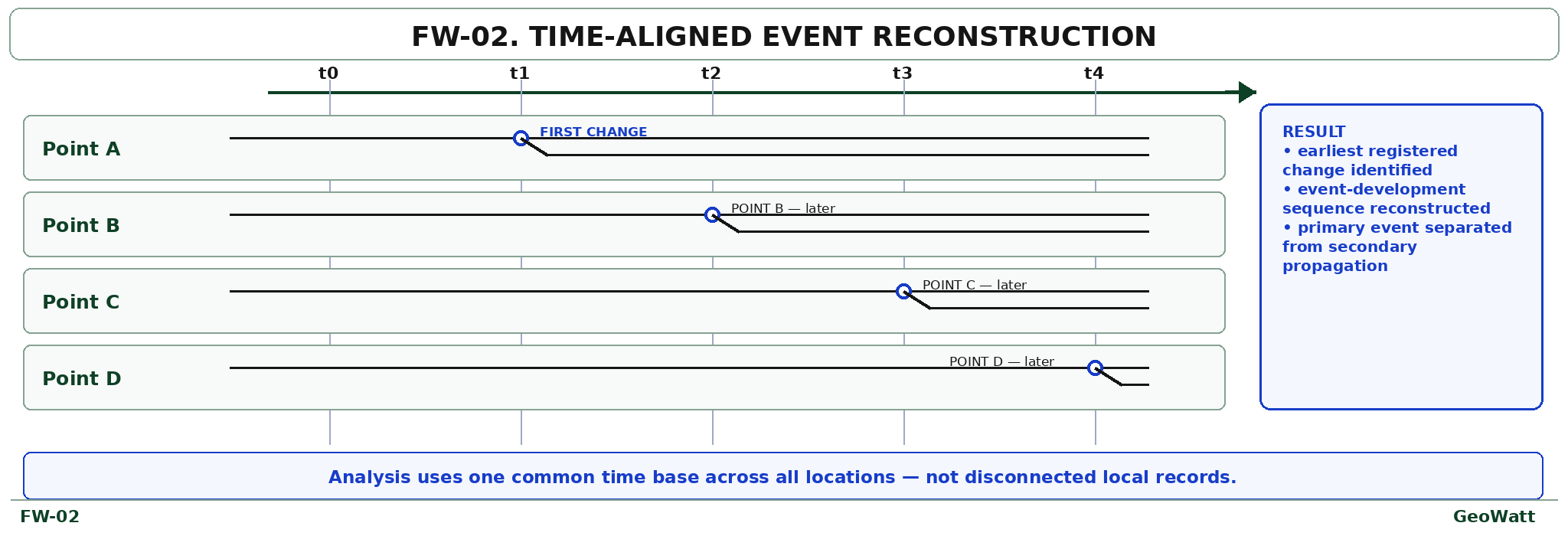
Functional result for a dispatch centre
The synchronized DES data set helps answer engineering questions about event development without replacing the dispatcher's operational conclusion.
| Engineering question | What can be determined |
|---|---|
| First change | The earliest registered change on the common time base. |
| Operating-state change | Changes in I/U, P/Q, frequency, and phase relationships at connected nodes. |
| Spatial localization | The section or location where the earliest operating-state change was recorded. |
| Event sequence | Direct comparison of remote measurements as the transient process develops. |
| Protection and remedial action | The timing and sequence of protection and remedial-action operation. |
| Post-disturbance state | The condition of the remaining interconnections after event development. |
Technical parameters
The following values define the initial engineering basis. Synaptec confirms the final configuration from project-specific input data.
| Parameter | Value or characteristic |
|---|---|
| Measurements | Current, voltage, synchronized waveforms, frequency, phase relationships, and diagnostic harmonic content. |
| Waveform publication | 4 or 4.8 kHz. |
| Timestamping | Up to 1 µs. |
| Passive sensing segment | Up to 60 km—the limit of one passive segment, not the complete system. |
| Segment optical budget | Less than 10 dB from the first to the last sensor. |
| PSC-1-C loss guideline | Approximately 0.2 dB per sensor. |
| Monitoring PSC | 18 recommended, 24 maximum per DES Interrogator. |
| Protection PSC | 12 recommended, 18 maximum per DES Interrogator. |
| Interfaces | IEC 61850-9-2 SV, GOOSE, and MMS. |
| DES Interrogator | 19-inch, 3U; 447 × 425 × 132 mm; 8.3 kg; up to 90 W; −25 to +55 °C; IP20. |
Measurement-point selection
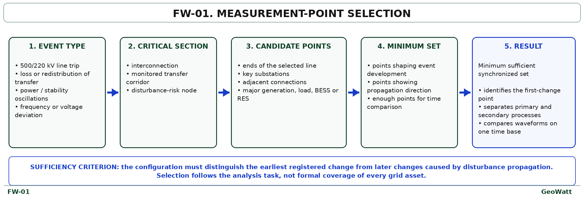
Points are selected from the analysis objective rather than by formally covering every grid asset: event type → critical electrical section → required parameters → candidate measurement points → minimum sufficient set.
A configuration is sufficient when it can distinguish the earliest registered change from later changes caused by disturbance propagation.
Integration and engineering boundaries
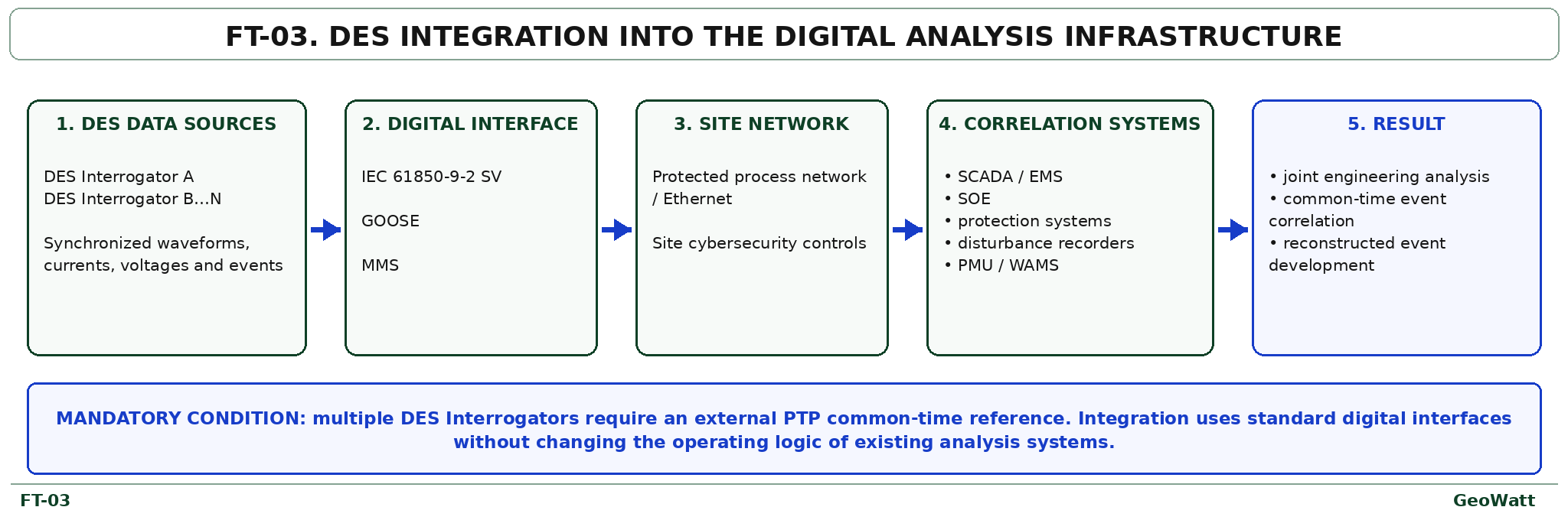
DES adds a synchronized I/U and waveform measurement layer. It does not replace existing SCADA/EMS, PMU/WAMS, protection and remedial-action systems, disturbance recorders, or operational dispatch procedures.
- Multiple DES Interrogators require one external common-time source, such as PTP.
- Data is transferred through standard IEC 61850-9-2 SV, GOOSE, and MMS interfaces.
- Storage and transmission architecture is defined by the site's cybersecurity and operational requirements; a cloud architecture is not mandatory.
- Waveforms and harmonic content form a diagnostic layer; compliance with power-quality metrology requirements must be confirmed separately.
Regulatory context
Distributed synchronized monitoring supports the general direction of Kazakhstan and Uzbekistan requirements for operating-state supervision, recording of pre-fault and fault processes, sequence-of-events analysis, protection and remedial-action performance, and transmission of telemetry to dispatch centres.
Further project development
The recommended engineering sequence is: selected electrical section → representative event type → required parameters → measurement locations → available optical infrastructure → common time synchronization → Synaptec-confirmed configuration → correlation with dispatch-centre data.
Referenced regulatory and technical documents
- CDC Energia and the Central Asian Power System materials;
- Resolution No. 609 of the Cabinet of Ministers of the Republic of Uzbekistan dated 18 October 2022;
- Law of the Republic of Kazakhstan On Electric Power Industry;
- Rules for Technical Operation of Power Plants and Networks of the Republic of Kazakhstan, Order No. 247 dated 30 March 2015;
- Grid Code of the Republic of Kazakhstan;
- Rules for Preventing Emergency Disturbances in the Unified Power System of Kazakhstan, Order No. 58 dated 2 February 2015;
- Electrical Installation Code of Kazakhstan; GOST 32144-2013, GOST 30804.4.7-2013, GOST 30804.4.30-2013, and GOST 33073-2014;
- IEC 61850-9-2, IEC 61850 GOOSE, and MMS;
- Synaptec MA-010 Rev.19, PSC documentation, and Synaptec technical clarification dated 19 August 2026.